


2026 Best Worm Gears for Global Buyers?

Worm Gears remain a practical choice when machinery needs substantial speed reduction in a compact space. For global buyers, the best option in 2026 is not simply the one with the lowest quoted price. It is the gear set that matches the application, operating conditions, and supplier’s demonstrated capabilities.

A useful comparison starts with the required ratio, input speed, torque, duty cycle, and available mounting space. Material choices matter, too. A bronze wheel paired with a hardened steel worm may suit some demanding applications, but suitability depends on load, lubrication, heat, and service intervals. Ask for dimensional drawings, stated efficiency, backlash information, and inspection records. A neat catalog is not proof of consistent production. Request evidence that relates to the actual model being quoted.

Global sourcing adds practical questions. Can the supplier confirm tolerances, packaging, lead times, and technical support in writing? Are spare parts available? Check whether samples or test reports can help verify fit before placing a larger order. Small errors matter. A slightly mismatched center distance can complicate installation, while poor lubrication can shorten service life. No shortlist can settle every case; real operating data is often incomplete, and supplier claims deserve careful review. This guide compares selection criteria and buying considerations so readers can judge available Worm Gears against their own equipment needs—not a universal ranking.
2026 Best Worm Gears for Global Buyers?

Worm Gear Fundamentals: Right-Angle Shafts, Sliding Contact, and High Ratios

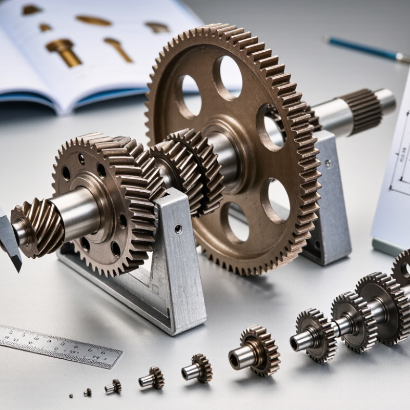
Worm gears pair a screw-like worm with a toothed wheel, usually turning shafts through 90 degrees. This layout fits compact drives where space is limited. One input turn can produce a small output movement, so a single stage can provide a high reduction ratio. That is the appeal.

Unlike many gear pairs, worm teeth slide across one another as they mesh. This sliding contact can create heat and friction, especially under continuous load or poor lubrication. A gearbox that feels quiet at low speed may still run hot after an hour. Check lubricant type, fill level, operating temperature, and duty cycle against the supplier’s specifications. Not optional.

Right-angle output and high ratios do not guarantee a good fit. Efficiency may be lower than with some other gear arrangements, and self-locking should never be assumed from appearance alone. Lead angle, load, lubricant, wear, and vibration all matter. Measure the shaft arrangement and mounting space, then compare rated torque and thermal limits. It is easy to overvalue compactness. A slightly larger reducer may waste less energy and last longer in a hot, nonstop application.
Ratio and Efficiency: Compare Common 5:1–100:1 Ratios and 50–90% Efficiency

Worm gear ratios commonly range from 5:1 to 100:1. A 5:1 reduction suits applications that need moderate speed control. A 100:1 ratio can deliver much slower output from a faster motor. The higher ratio does not create torque without limits; losses, shaft loads, and motor capacity still matter. Match the ratio to the required output speed, not just the largest number on a product sheet.

Efficiency often falls within a broad 50–90% range, but the actual figure depends on gear geometry, materials, lubrication, speed, and load. In many designs, higher reduction ratios bring more sliding contact and greater friction. That can mean more heat and lower efficiency. Heat tells a story. A gearbox that runs hot may need a different ratio, lubricant, or operating cycle. A tidy percentage can still mislead if the test conditions are missing.

When comparing suppliers, ask how efficiency was measured and at what input speed, load, and temperature. Compare figures tested under similar conditions. For a conveyor running for hours, even a small efficiency difference can affect energy use and operating temperature. For intermittent positioning, compact size or a high reduction ratio may matter more. I would not choose from ratio alone; the real duty cycle often changes the answer.

2026 Worm Gear Ratios and Indicative Efficiency

Worm gear reducers are commonly offered in ratios from around 5:1 to 100:1. The ranges below are illustrative benchmarks, not guaranteed specifications. Actual efficiency depends on factors including worm lead angle, materials, lubrication, speed, load, and operating conditions.

How to read this: Each pair of bars shows an indicative lower and upper efficiency estimate for a ratio. Higher reduction ratios often have lower efficiency, but the ratio alone does not determine performance. Check the manufacturer's rated data for the specific operating point.

Load Capacity: Apply ISO 14521 Calculations to Worm Gear Selection

For global worm-gear selection, load capacity should come from the duty cycle, not a catalogue headline.
ISO 14521:2010 provides calculation methods for cylindrical worm-gear capacity, including checks related to tooth strength and surface durability. AGMA 6022-C93 also offers design guidance for cylindrical worm gearing. Neither gives one safe torque rating for every application. Geometry, materials, lubrication, speed, and temperature all change the result.

Start with the real output torque, not just motor power. Record starts per hour, shock loads, daily operating time, and the highest gearbox oil temperature. A 30:1 ratio may suit a compact conveyor, but frequent starts can raise tooth loads and heat.

Small details matter. Ask for the calculation inputs and the assumed service factor; compare them with your actual duty. If a rating omits lubricant, operating temperature, or life assumptions, treat it cautiously. That caveat is easy to miss.

A calculated rating is only as dependable as its inputs, and ISO 14521 is a method—not a substitute for checking alignment, mounting stiffness, and maintenance conditions.

Materials and Lubrication: Match Gear Alloys and ISO VG Oil to Duty

Worm gear performance begins with the contact pair, not the lubricant alone. A hardened steel worm commonly runs against a bronze wheel, which helps manage sliding contact and reduce seizure risk. For dusty, shock-loaded service, check wheel alloy, shaft hardness, and housing stiffness together. A softer bronze grade may tolerate impact better, but it can wear faster under sustained heavy loads. Details matter.

Choose ISO VG oil by operating temperature, sliding speed, load, and the gear maker’s guidance. A slow, heavily loaded unit may need a higher-viscosity oil, while cold starts can make that oil sluggish. ISO VG 220 or 320 may suit some applications, but neither is a universal answer. Check the oil’s temperature-viscosity data and confirm it is compatible with the gear metals and seals. If the housing runs hot, measure it after a representative duty cycle, not only at startup.

Lubrication needs practical checks. Look for leaks, foaming, unusual noise, and darkened oil; inspect more often during commissioning. Some synthetic oils can improve efficiency or service life, yet material compatibility and cost deserve review. There is no perfect chart for every machine. I would rather verify temperature and wear after a few weeks than trust a neat estimate that ignores real operating conditions.

2026 Best Worm Gears for Global Buyers? - Materials and Lubrication: Match Gear Alloys and ISO VG Oil to Duty

A practical comparison of common worm-gear material pairings and lubricant starting points. ISO VG selections are indicative; confirm the gear maker’s instructions, operating speed, load, temperature, seals, and lubrication method before use.

Duty profile Typical worm material Typical wheel material Lubricant starting point Selection notes
General industrial duty; moderate speed and load Hardened alloy steel Tin bronze, such as CuSn12 Worm-gear oil; commonly ISO VG 220 or 320, subject to operating conditions For bronze wheels, use an oil confirmed as compatible with copper alloys. Avoid unverified active-sulfur EP formulations.
Low speed, high load, or sustained operation Hardened alloy steel Tin bronze or a specified high-strength bronze Often ISO VG 320 or 460 as an initial range; verify against the gearbox specification Higher viscosity may support film formation at low speed, but can increase churning losses and operating temperature.
Higher speed or cooler ambient conditions Hardened alloy steel Tin bronze ISO VG 150 or 220 may be considered where permitted by the gear maker Do not reduce viscosity solely to improve cold starting; check the minimum operating temperature and required film thickness.
High ambient temperature or demanding continuous duty Hardened alloy steel Tin bronze or specified aluminum bronze A suitable synthetic worm-gear oil; ISO VG 320 or 460 may be specified for some designs Check thermal stability, copper-alloy compatibility, seal materials, and the oil maker’s temperature limits.
Quiet, light-load, intermittent service Steel or stainless steel, as designed Engineering polymer, such as POM or nylon, where specified Use only the lubricant approved for the polymer and gearbox; do not assume a standard ISO VG oil is suitable Check polymer compatibility, temperature limits, moisture effects, and whether the unit is designed for grease or oil lubrication.
ISO VG reference: ISO viscosity grades classify industrial lubricant viscosity by kinematic viscosity at 40°C. For example, ISO VG 220 is 198–242 mm²/s, ISO VG 320 is 288–352 mm²/s, and ISO VG 460 is 414–506 mm²/s. These grades alone do not determine suitability; follow the gearbox manufacturer’s specified lubricant and change interval.

Global Buyer Checks: Verify ISO 9001, IEC 60034, Torque, and Backlash

For a 2026 worm-gear purchase, treat certificates as evidence to inspect, not a shortcut. Request a current ISO 9001 certificate and check the listed company, site, scope, and expiry date. ISO 9001 covers a supplier’s quality management system; it does not certify a gearbox’s torque or service life. For the motor, review applicable IEC 60034 documents, including rated power, speed, duty, and thermal details. Compare them with your supply frequency and operating cycle. Paperwork can look complete. One mismatch matters.

Ask for output torque at your actual input speed, duty cycle, and mounting position, not just a headline rating. Confirm whether the figure is continuous or intermittent, and discuss shock loads and heat. For backlash, request a stated value and measurement method. Check whether it was measured at the output shaft and under a defined condition; otherwise, comparisons may mislead. A simple test can reveal more than a polished table: with power isolated, gently reverse the output and measure its free movement. Small differences matter. I would still allow some uncertainty, since temperature, wear, and setup can change readings after installation. Keep the test conditions with the quotation.

Packaging machine ROI calculator

Need help figuring out if packaging automation is right for your business?


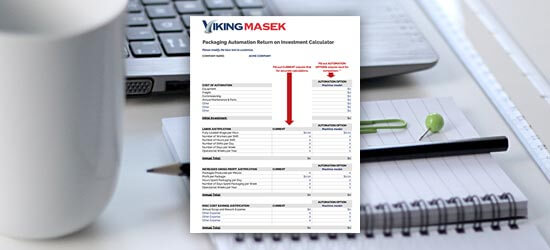
First, start with the numbers. Download our free packing machine ROI calculator to learn how long it will take for an investment in automation to pay for itself (and much more).


Free packaging automation ROI calculator