


Why Choose a Flanged Type Globe Valve?
Industrial facilities rarely choose valves by appearance alone. Flow stability, maintenance access, leakage control, and pressure ratings all influence lifecycle performance. A Flanged Type Globe Valve deserves attention because its guided disc can regulate flow with useful precision. Its bolted flange connection also supports predictable installation and removal around pumps, boilers, and process skids.
The International Energy Agency reports that industry uses roughly 37% of global final energy. Small efficiency losses can therefore become significant operating costs. A properly selected globe valve can help control steam, water, oil, and other compatible fluids. Its design offers a practical balance between throttling capability and shutoff performance. That matters in lines where operators adjust flow repeatedly, not just during emergencies.
Engineering confidence must come from standards, not marketing claims. ASME B16.5 provides recognized flange dimensions and pressure-temperature guidance. API 623 establishes requirements for steel globe valves used in demanding process service. ISO 15848-1 also addresses fugitive emissions testing for industrial valves. These references help engineers compare materials, end connections, packing systems, and inspection records.
Still, no valve is universally right. A globe valve usually creates more pressure drop than a full-bore gate valve. It may also require greater installation space and a higher initial budget. That trade-off is easy to underestimate. Site experience shows that access, actuator orientation, fluid cleanliness, and maintenance habits can decide the real result. Careful sizing remains essential. A small mistake becomes a hot flange, noisy trim, or unstable flow. For that reason, selecting a Flanged Type Globe Valve should combine process calculations, applicable standards, supplier documentation, and honest review of operating conditions.
What Is a Flanged Type Globe Valve?
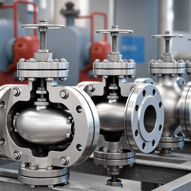
A flanged type globe valve is an industrial valve designed to regulate or stop fluid flow. Its body uses two flanges, bolted to matching pipeline flanges with a gasket between them. Inside, a movable disc travels toward a stationary seat. This vertical movement creates accurate throttling, unlike a simple quarter-turn isolation valve. The valve often appears in steam, water, oil, and chemical process lines.
Its flanged connection supports firm alignment and easier removal during maintenance. However, installation still requires careful bolt tightening and gasket selection. ASME B16.5 defines common flange dimensions and pressure classes, while ASME B16.34 addresses valve pressure-temperature ratings and testing requirements. These standards do not make every valve suitable for every service. Material compatibility remains critical.
Field technicians usually select globe valves where flow control matters more than low resistance. The internal S-shaped passage produces a noticeable pressure drop. The U.S. Department of Energy’s steam-system guidance commonly uses a 5–20% range when screening distribution losses, so poor valve selection can waste energy. That figure is not a valve-specific guarantee. Real losses depend on pipe length, pressure, temperature, and operating practice. A flanged globe valve may offer dependable control, but its heavier body and larger actuator can complicate tight spaces. That trade-off deserves honest review.
How Does a Flanged Globe Valve Work?
A flanged globe valve controls fluid by moving a disc toward or away from a fixed seat. The handwheel turns a threaded stem, converting rotation into precise vertical movement. When the disc lifts, the passage opens. When it presses against the seat, flow stops.
The fluid changes direction inside the valve body, usually passing beneath or beside the disc. This design creates resistance, but it also supports accurate throttling. Operators can adjust steam, water, oil, or compressed air more gradually than with many quarter-turn valves. The flanged ends connect to matching pipe flanges with bolts and a gasket. Correct alignment matters. Uneven tightening can damage the gasket or create a slow leak.
In field inspections, I check stem movement, packing condition, flange bolts, and unusual vibration. A stiff handwheel may indicate corrosion, excessive packing pressure, or debris near the seat. Do not force it. That mistake can bend the stem or damage the sealing surfaces. Globe valves are reliable when selected for the correct pressure, temperature, and fluid. However, they are not perfect for every line. Their pressure drop may waste energy in high-flow systems, and poor installation can defeat good valve design. Regular inspection remains necessary, even when the valve appears sound.
Why Choose a Flanged Type Globe Valve? - How Does a Flanged Globe Valve Work?
| Data Dimension | Typical Information | Why It Matters |
|---|---|---|
| Valve Type | Linear-motion globe valve with flanged end connections | It combines controlled flow regulation with a bolted, detachable connection suitable for permanent piping systems. |
| How It Works | A handwheel or actuator moves the stem and disc vertically toward or away from the seat. | The disc position changes the opening area, allowing the valve to stop, start, or regulate fluid flow. |
| Flow Path | The fluid changes direction inside the body and passes between the disc and seat. | The changing direction improves throttling control but creates more pressure loss than a fully open gate or ball valve. |
| Primary Function | Shutoff, throttling, and flow control | Globe valves are well suited to applications where flow must be adjusted frequently or accurately. |
| Flanged Connection | The valve is joined to the pipeline with matching flanges, gaskets, and bolting. | Flanges support straightforward installation, alignment, inspection, removal, and maintenance without cutting the pipe. |
| Common Pressure Classes | ASME Class 150, 300, 600, 900, 1500, and 2500 are commonly specified ranges; availability depends on design and size. | The selected pressure class must match the design pressure, temperature, flange standard, and applicable piping code. |
| Typical Sizes | Commonly manufactured in nominal pipe sizes from approximately NPS 1/2 to NPS 24, with larger sizes available for selected designs. | The actual size range depends on pressure class, body pattern, material, end standard, and service requirements. |
| Flow-Control Capability | Generally better throttling performance than gate valves because the disc position can be adjusted progressively. | This makes the design useful for steam, cooling water, process fluids, and other services requiring controlled flow. |
| Shutoff Performance | A properly selected and maintained valve can provide reliable shutoff; leakage performance depends on the seat design and applicable testing standard. | Seat material, surface finish, pressure differential, temperature, and maintenance all affect shutoff performance. |
| Pressure Drop | Typically higher than a full-bore gate or ball valve when open because of the internal flow path and seat arrangement. | Higher pressure loss should be considered when calculating pump head, energy consumption, and system capacity. |
| Operating Torque and Travel | The stem generally requires multiple turns for manual operation, while actuators provide controlled linear travel. | The operating method should be selected according to valve size, differential pressure, cycle frequency, and automation requirements. |
| Typical Body Materials | Carbon steel, stainless steel, ductile iron, cast iron, and alloy steels are used for different services. | Material selection must consider fluid compatibility, corrosion resistance, pressure, temperature, and mechanical loading. |
| Seat Options | Metal seats are common for high-temperature or abrasive service; resilient or engineered seats may be used where compatible. | The seat design influences leakage class, temperature capability, wear resistance, and maintenance intervals. |
| Installation Position | Many globe valves can be installed in horizontal or vertical piping, subject to the manufacturer’s flow-direction and actuator requirements. | Correct orientation helps prevent improper loading, reduces wear, and supports safe access for operation and maintenance. |
| Typical Applications | Steam systems, boiler feedwater, cooling water, chemical processing, oil and gas facilities, power plants, and industrial utilities. | The design is valuable where dependable isolation and repeatable flow adjustment are both required. |
| Main Advantages | Good throttling control, robust construction, accessible maintenance, and strong suitability for high-pressure services. | These features make a flanged globe valve a practical choice for demanding process and utility piping. |
| Main Limitations | Higher pressure loss, larger installation length than some valve types, and greater actuator force requirements in certain services. | A different valve design may be more efficient when minimum pressure drop, compact dimensions, or frequent full-bore flow is the priority. |
Note: Pressure ratings, size ranges, materials, temperature limits, and leakage performance vary by valve design, applicable standards, fluid service, and operating conditions.
What Are the Main Benefits of Flanged Connections?
Why Choose a Flanged Type Globe Valve?
Flanged connections make globe valve installation practical in demanding process systems. ASME B16.5 specifies flange dimensions, pressure classes, and temperature limits. This standardization supports safer selection across different piping layouts. Technicians can also remove a flanged valve without cutting the pipe. That matters during shutdowns, inspections, and emergency repairs.
The U.S. Department of Energy reports that industrial steam systems can lose significant energy through leaks and poor maintenance. A correctly assembled flange helps reduce this risk around valve joints. It also allows gasket replacement when thermal cycling causes compression loss. According to Grand View Research’s Industrial Valves Market Report, the global market was valued at more than USD 78 billion in 2023. The figure reflects continued demand for reliable flow-control equipment. Still, flanges are not automatically safer. Uneven bolt tightening can distort the gasket and create a small, persistent leak. Field maintenance often reveals this uncomfortable detail.
Tips: Clean both flange faces before assembly. Use the specified gasket material. Tighten bolts in a cross pattern with a calibrated torque wrench. Check alignment before applying force. A slightly longer inspection may prevent hours of downtime. Do not ignore rust staining near the joint. It can be an early warning, though not always. Record torque values and retest after the first heating cycle.
Why Choose a Flanged Type Globe Valve?
Standardized pressure classes available for flanged valve connections
Flanged connections are widely used because they create a strong, standardized, and serviceable joint. The bolted design allows the valve to be removed for inspection or maintenance, while the gasketed seal helps control leakage. ASME B16.5 commonly defines pressure class designations from Class 150 through Class 2500. Actual allowable working pressure depends on temperature, material, valve design, gasket selection, and applicable standards.
Where Are Flanged Globe Valves Commonly Used?
Why Choose a Flanged Type Globe Valve?
Where Are Flanged Globe Valves Commonly Used?
Flanged globe valves are common in process piping where dependable flow control matters. Their bolted connections suit medium and large pipelines, especially where regular maintenance is expected. Engineers often specify them for steam lines, cooling water systems, chemical processing, and industrial heating circuits. The globe valve’s internal disc moves toward the seat, allowing gradual adjustment instead of simple isolation. This makes it useful near boilers, heat exchangers, pumps, and pressure-reducing stations. It is not always the fastest valve, but controlled throttling is often more valuable.
In water treatment plants, flanged globe valves may regulate dosing lines, filtered water, or backwash flow. Manufacturing facilities also use them for compressed air, hot oil, and utility services. Their rigid flange connection helps manage vibration and supports accurate alignment during installation. However, the valve still needs suitable materials, pressure ratings, and gasket selection. A poor match can cause leakage, difficult operation, or premature seat damage. Field checks often reveal a simple mistake: the valve is correctly sized, but installed where constant throttling creates excessive wear.
How Should You Select the Right Flanged Globe Valve?
Why Choose a Flanged Type Globe Valve?
How Should You Select the Right Flanged Globe Valve?
Selecting a flanged globe valve starts with the fluid, not the flange size. Identify whether the medium is water, steam, gas, oil, or a corrosive chemical. Check its temperature, pressure, viscosity, and possible solid content. These details affect the body material, seat design, and packing choice.
Match the valve pressure class to the system’s maximum working pressure. Do not rely only on the normal operating value. Short pressure surges can matter. Confirm the flange standard, nominal diameter, and face-to-face dimension before ordering. A mismatch may cause installation delays or unsafe temporary modifications.
Think about control requirements. Globe valves provide reliable throttling, but excessive pressure drop can waste energy. For frequent adjustment, examine the flow coefficient and trim design. For basic isolation, a simpler configuration may be more practical. Select stainless steel, alloy steel, or another suitable material after reviewing corrosion data. Material charts help, but real operating conditions can be less predictable.
Consider handwheel access, actuator clearance, mounting direction, and maintenance space. A valve that fits the pipe may still be difficult to service. Ask for pressure-test records, material certificates, and inspection details from a qualified supplier. These documents support traceability and confidence.
One point deserves caution. Bigger is not always better. Oversizing can reduce control accuracy and create unstable flow. Review the valve with process engineers and maintenance staff, then compare the technical data with actual site conditions. My checklist would also include drain points and replacement access, although these are easy to overlook.


