


Why Choose a Pressure Relief Valve?
Choosing a Pressure Relief Valve is not merely a purchasing decision. It is a safeguard against overpressure, equipment damage, production loss, and serious workplace hazards. In a functioning plant, pressure can rise quietly inside a boiler, vessel, pipeline, or compressor system. A correctly selected valve responds before that pressure exceeds the equipment’s safe design limits.
Trevor Kletz, a respected process-safety author, is often credited with saying, “If you think safety is expensive, try ignorance.” His warning applies directly to pressure protection. A valve that opens too late, closes poorly, or lacks suitable materials can create hidden risks. The label alone proves little. Engineers must examine set pressure, relieving capacity, temperature, backpressure, fluid compatibility, discharge routing, and maintenance access. Small details matter. A blocked outlet can defeat a well-designed system.
A reliable Pressure Relief Valve also supports operational confidence. It can protect a stainless-steel vessel from deformation, prevent repeated shutdowns, and help operators respond to abnormal conditions. However, no valve can compensate for poor inspection or unclear procedures. That is an uncomfortable point, but it deserves attention. Real-world performance depends on sizing calculations, installation quality, periodic testing, and competent technicians. The best choice is therefore not always the cheapest valve or the most familiar brand. It is the valve that matches the actual process, documented standards, and credible engineering judgment. When pressure behavior is uncertain, careful analysis should come before purchasing.
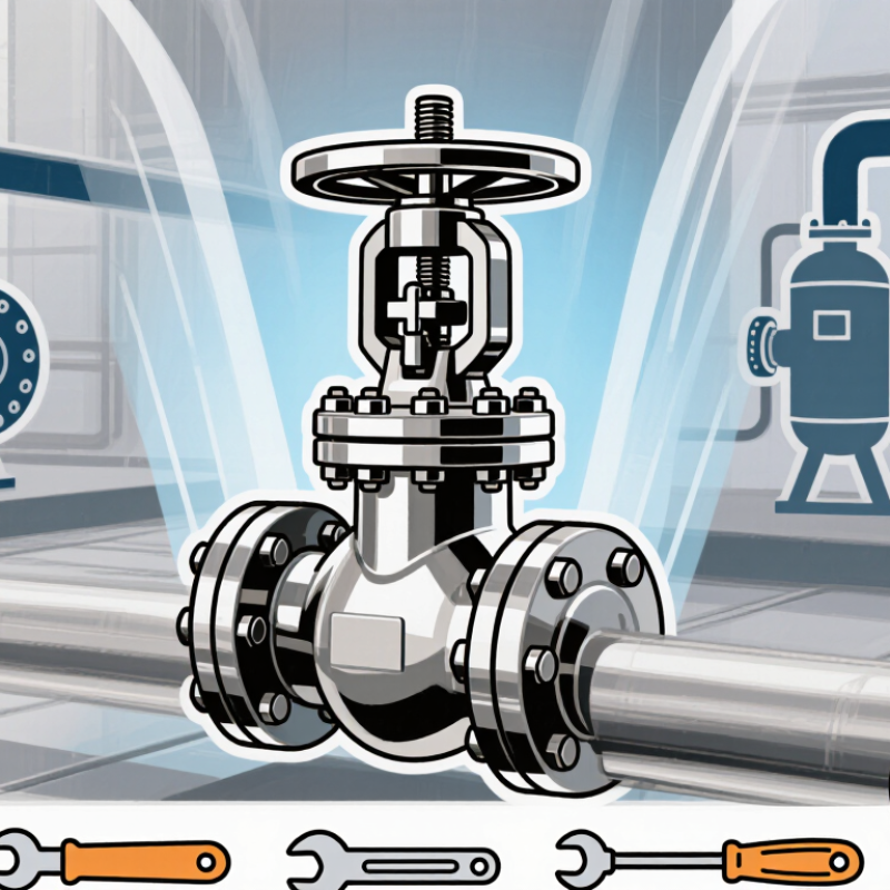
What a Pressure Relief Valve Is and How It Works
Why Choose a Pressure Relief Valve?
A pressure relief valve protects equipment when pressure rises beyond a safe limit. It remains closed during normal operation. When pressure reaches its set point, the spring, pilot, or rupture mechanism responds. The valve then opens, releasing fluid to a safe destination. Once pressure falls, it reseats, although leakage or improper maintenance can prevent a perfect seal.
Correct selection requires more than matching pipe size. Engineers assess set pressure, relieving capacity, temperature, fluid properties, backpressure, and discharge routing. ASME Boiler and Pressure Vessel Code Section VIII provides design requirements. API 520 and API 521 offer sizing and installation guidance for process systems. A practical inspection lesson is simple: a relief valve needs a clear inlet, a suitable outlet, and documented testing. Small errors matter.
Incident reports show why this protection deserves attention. The Buncefield Major Incident Investigation Board reported 43 injuries after a fuel-storage overfill and vapor-cloud explosion in 2005. The U.S. Chemical Safety Board’s Texas City refinery investigation recorded 15 deaths and 180 injuries. Those reports emphasized weak safeguards and poor process control. A pressure relief valve cannot correct every design failure. It can, however, reduce the chance of vessel rupture when other controls fail. The choice should reflect real operating conditions, not only catalog ratings. That detail matters.
How Pressure Relief Valves Prevent System Damage
Why Choose a Pressure Relief Valve?
A pressure relief valve helps prevent system damage when pressure rises beyond a safe limit. It opens automatically at its set pressure. Excess fluid then leaves through a controlled discharge path. This action protects vessels, piping, pumps, and connected instruments from dangerous stress.
During equipment inspections, technicians often find that pressure spikes happen faster than operators can react. A blocked outlet, sudden temperature change, or failed control component may create this risk. The valve provides a final mechanical safeguard. However, it cannot fix poor system design. Incorrect sizing can delay opening or release too much fluid. Set pressure must match the equipment’s allowable working pressure. Discharge piping also needs proper support and safe routing.
Tips: Check the valve’s set pressure, sizing, and discharge direction before installation. Keep the outlet clear. Inspect seals and corrosion during scheduled maintenance. Test the valve under approved procedures, not by forcing the handle. Small mistakes matter. I once underestimated vibration near a relief valve; the connection loosened over time. That detail changed our inspection checklist. Records should include test dates, pressure settings, visible damage, and corrective work. A reliable protection plan combines the valve with alarms, sound operating limits, and trained personnel.
Why Choose a Pressure Relief Valve? - How Pressure Relief Valves Prevent System Damage
| System or Equipment | Typical Operating Pressure | Representative Relief Setting | Pressure Hazard | How the Valve Prevents Damage | Primary Protection Benefit |
|---|---|---|---|---|---|
| Compressed-air receiver | 8 bar(g) | At or below the vessel’s maximum allowable working pressure, commonly around 9–10 bar(g) for this example | Blocked outlet, compressor malfunction, or excessive heating | Opens automatically when system pressure reaches the calibrated set pressure and discharges excess air | Reduces the risk of vessel rupture and damage to connected equipment |
| Steam or hot-water system | 6–16 bar(g) | Selected in accordance with the boiler, vessel, or piping design pressure | Thermal expansion, loss of circulation, or closed isolation valves | Relieves steam or hot water before pressure exceeds the allowable design limit | Protects boilers, heat exchangers, piping, and personnel from overpressure events |
| Hydraulic power unit | 140–210 bar(g) | Usually set below the rated pressure of the weakest protected component | Actuator stall, blocked flow, or sudden load increase | Diverts hydraulic fluid back to the reservoir when the pressure threshold is exceeded | Prevents hose bursts, seal failure, pump overload, and actuator damage |
| Process pipeline | Depends on the process fluid and pipe rating | Set below the pressure rating of the protected piping and equipment | Pump deadheading, control-valve failure, or rapid valve closure | Releases or redirects fluid to a safe location when pressure rises above the set point | Limits mechanical stress, vibration, leakage, and pipe or fitting failure |
| Storage tank | Near atmospheric pressure or low pressure | Configured separately for pressure and vacuum protection | Tank filling, vapor generation, blocked vents, or liquid withdrawal | Relieves excess pressure and, where required, admits air or inert gas during vacuum conditions | Prevents tank deformation, collapse, product loss, and hazardous releases |
| Refrigeration system | Typically 5–30 bar(g), depending on refrigerant and temperature | Based on refrigerant properties, equipment design pressure, and applicable safety requirements | Condenser blockage, fire exposure, or trapped liquid thermal expansion | Discharges refrigerant when pressure reaches the approved protection threshold | Protects compressors, condensers, vessels, and refrigerant circuits from overpressure |
Common Types of Pressure Relief Valves
Why Choose a Pressure Relief Valve?
Common Types of Pressure Relief Valves
Pressure relief valves protect vessels, pipelines, and process equipment from dangerous overpressure. Their purpose is simple: release pressure before equipment fails. Choosing the correct type requires more than checking the set pressure. Temperature, fluid properties, discharge capacity, and maintenance access also matter.
The spring-loaded relief valve is widely used because its design is compact and relatively easy to inspect. A calibrated spring holds the valve closed until pressure reaches the selected setting. These valves suit many liquid and gas systems. However, back pressure can affect performance, especially in discharge piping with poor design.
Pilot-operated relief valves use system pressure to control opening and closing. They can provide accurate operation in high-pressure applications. They may also perform well where pressure fluctuations are common. Their pilot system needs clean, compatible media. Small blockages can create serious operating problems.
Balanced bellows valves reduce the influence of back pressure on the spring mechanism. They are useful when discharge pressure changes during operation. Vacuum relief valves work differently. They admit air or another approved gas when internal pressure falls too low. This prevents tanks from collapsing under vacuum conditions. Selecting one requires careful review of the vessel design.
During inspections, technicians should check leakage, corrosion, set pressure, and discharge routing. I have seen systems fail because the valve was correctly rated but poorly installed. That detail is easy to underestimate. No selection is perfect. A practical decision should combine calculations, operating experience, and applicable safety standards.
Key Factors for Choosing the Right Valve
Choosing a pressure relief valve begins with understanding the system, not the valve catalog. The valve must open at a safe set pressure and discharge enough fluid during the worst credible event. That requires real operating data. Record normal pressure, temperature, fluid composition, and possible pressure surges. A small mismatch can cause leakage, chattering, or dangerous overpressure. Set pressure should remain below the equipment’s allowable working pressure, with local code requirements checked by a qualified engineer. Capacity calculations should consider blocked outlets, fire exposure, thermal expansion, and other credible cases. Do not guess here. A recurring lesson from plant reviews is that old specifications sometimes remain unchanged after the process shifts. That shortcut deserves a second review.
Material selection follows the fluid and temperature. Corrosive, viscous, or contaminated media may need different trim, seals, or valve designs. Confirm compatibility using documented data, not appearance or habit. Check inlet and outlet piping carefully. Excessive inlet pressure loss can make the valve flutter, while backpressure can reduce discharge performance. The discharge line should be supported, drained where appropriate, and routed away from people and equipment. Spring-loaded and pilot-operated valves behave differently, especially in dirty service. Choose the simplest suitable design, but do not oversimplify the risk. Verify certificates, test procedures, inspection intervals, and maintenance access before purchase. A valve that fits on paper may be awkward to remove in a crowded plant. Field conditions matter. After installation, inspect the set pressure, seals, lifting device, and discharge path. Keep readable records. They often reveal problems before the next inspection.
Installation, Testing, and Maintenance Requirements
Why Choose a Pressure Relief Valve?
Installation, Testing, and Maintenance Requirements
A pressure relief valve protects equipment when pressure rises beyond a safe operating limit. Correct installation matters as much as valve selection. Check the set pressure against the vessel rating and process conditions. Install the valve in the recommended position, usually with a short, unobstructed inlet connection. The discharge line should lead to a safe location without creating back pressure. Never leave protective caps, debris, or paint inside the connection. Small errors can become serious.
I have seen maintenance teams overlook the inlet pipe during inspections. That is a costly oversight. Before commissioning, qualified personnel should verify the set pressure, flow direction, and discharge arrangement. Testing requires calibrated equipment and documented results. A controlled lift test can confirm opening pressure, while a leak check confirms proper reseating. If the valve fails to open or reseat correctly, remove it from service and investigate the cause. Do not adjust the spring casually.
Maintenance should follow applicable codes, site procedures, and the valve manufacturer’s instructions. Inspect for corrosion, deposits, damaged threads, blocked outlets, and evidence of leakage. Process conditions may require more frequent testing than a calendar schedule suggests. Keep records of inspection dates, test pressure, findings, and corrective work. A clean exterior does not prove reliable operation. Sometimes, the hidden problem is inside. Revisiting the maintenance interval after each failure or process change is sensible, even when the original plan seemed adequate.
Why Choose a Pressure Relief Valve? — Installation, Testing, and Maintenance Requirements
Pressure relief valves protect pressurized equipment from exceeding its allowable pressure. Correct installation, calibrated testing, and regular maintenance are essential for reliable overpressure protection.
Maximum set-pressure deviation shown according to ASME BPVC Section VIII, Division 1, UG-134: ±2 psi for set pressures up to and including 70 psi, and ±3% for set pressures above 70 psi. The 100 psi example therefore permits a maximum deviation of 3 psi.
Installation
Use correctly sized inlet and discharge piping, minimize flow restrictions, support the valve independently, and install it in a position that allows inspection and removal.
Testing
Verify the set pressure with calibrated equipment after installation, adjustment, repair, or any event that may affect valve performance. Record the test results.
Maintenance
Inspect for corrosion, deposits, leakage, blocked passages, and damaged components. Set inspection intervals according to service conditions, regulatory requirements, and documented operating history.


