


Why Choose a Dismantling Joint for Pipeline Systems?

Why Choose a Dismantling Joint for Pipeline Systems?

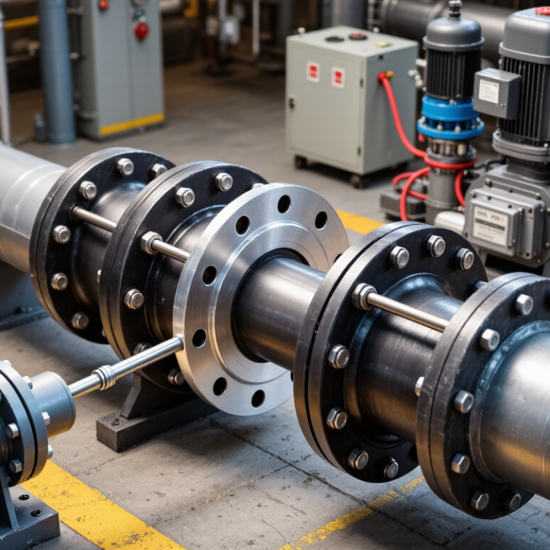
A Dismantling Joint gives maintenance teams controlled access to critical pipeline equipment. It connects flanged pipes, valves, pumps, meters, and other components. Its adjustable design also helps manage installation tolerances. That matters when pipe lengths are not perfectly accurate.

Pipeline engineer David Johnson states, “A dismantling joint earns its value when access is difficult, not when installation is easy.” This practical view reflects field experience. A valve may need removal after years of service. Corrosion may lock a flange connection in place. Without a Dismantling Joint, workers might cut pipe sections or use excessive force. Both options increase downtime and create unnecessary repair work.

A reliable joint transfers pipeline loads while preserving useful adjustment. During installation, technicians can set the required gap between flanges. They can then tighten the tie rods and complete a stable connection. This process is especially valuable inside crowded pump stations. Space is limited there. Every millimetre matters.

However, a Dismantling Joint is not a magic fitting. Engineers must verify pressure ratings, flange standards, gasket materials, and tie-rod settings. Poor alignment can still damage equipment. Incorrect tightening may cause leakage. That uncomfortable detail deserves attention.

When correctly specified, the joint supports safer maintenance and shorter shutdowns. It also reduces the risk of damaging expensive valves during removal. Operators gain flexibility without redesigning the entire pipeline. The best choice depends on the system, though. Site conditions, pipe material, movement, and maintenance history should guide the decision.
Why Choose a Dismantling Joint for Pipeline Systems?

What Is a Dismantling Joint in a Pipeline System?

A dismantling joint is a mechanical pipe fitting designed to connect, separate, and slightly adjust adjacent pipeline components. It usually includes flanged ends, a center sleeve, sealing gaskets, and tie rods. The tie rods transfer axial forces while the sleeve permits controlled movement during removal. In practical maintenance, this matters around valves, pumps, flow meters, and non-return devices. Technicians can loosen the assembly and create a working gap without cutting the pipe.

The U.S. Environmental Protection Agency’s 2023 Drinking Water Infrastructure Needs Survey estimates that drinking water systems require about $625 billion in investment over the next 20 years. Much of this need involves aging transmission and distribution assets. Dismantling joints do not solve aging infrastructure, but they can make planned replacement more predictable. A correctly selected joint helps installers manage flange alignment, gasket compression, and limited installation tolerances. Small details matter.

Not a magic component.

Site teams should verify pressure rating, pipe material, flange drilling, temperature, corrosion exposure, and required movement. The joint must also suit the restraint strategy. Otherwise, tie rods may be overloaded, or the pipeline may shift during operation. ISO 2531 and EN 545 provide relevant requirements for ductile iron pipeline components, but project specifications still require careful review. A common weakness is assuming every dismantling joint offers the same adjustment range. It does not. Field measurements, torque checks, and pressure testing remain essential. Mistakes often begin before installation.
How Dismantling Joints Simplify Pipeline Installation

Why Choose a Dismantling Joint for Pipeline Systems?

Pipeline installation becomes easier when future maintenance is considered at the trench stage. A dismantling joint connects flanged pipes, valves, pumps, and meters while allowing controlled axial adjustment. Installers can position equipment without forcing pipe sections into place. Later, technicians can remove a valve by loosening bolts and retracting the joint. No cutting torch. Less disruption.

This matters as infrastructure ages. The U.S. Environmental Protection Agency’s 2022 Clean Watersheds Needs Survey estimated $630.1 billion in wastewater infrastructure needs over 20 years. Its 7th Drinking Water Infrastructure Needs Survey identified another $625 billion requirement. The American Society of Civil Engineers also rated U.S. drinking water infrastructure C− in its 2021 report. Small installation decisions can affect long-term labor, downtime, and access.

On site, a dismantling joint can simplify alignment around a valve chamber, especially where space is tight. Workers should check flange ratings, gasket compatibility, bolt torque, and allowable movement. Installation tolerances still matter. A joint cannot correct poor surveying or unsupported pipe loads. That is the part people sometimes underestimate. In my experience, teams may focus on purchase cost and overlook removal time. A cheaper connection can become expensive when a seized valve blocks an entire line. Clear specifications and inspection records make the benefit more reliable. Oversight remains possible.

Key Benefits for Maintenance and Component Removal

Why Choose a Dismantling Joint for Pipeline Systems?

Key Benefits for Maintenance and Component Removal

A dismantling joint makes pipeline maintenance more controlled and less disruptive. Its adjustable center section creates working space between two flanged components. Technicians can remove a valve, pump, or meter without shifting long pipe sections. This reduces lifting effort and protects nearby supports, coatings, and flange faces. In crowded valve chambers, even a few extra centimeters can change the repair process.

The joint also helps manage installation tolerances. Pipe lengths are rarely perfect after years of settlement, vibration, or replacement work. By allowing controlled axial adjustment, it can reduce forced alignment during assembly. Tie rods help maintain the connection when designed and tightened correctly. However, they are not a substitute for proper pipe supports or pressure isolation. I have seen maintenance plans fail because workers treated adjustment space as unlimited. It is not.

Tips: Isolate and depressurize the line before loosening any bolts. Check the joint, gasket, tie rods, and flange faces for corrosion or damage. Mark the original position before adjustment. Use calibrated tools for bolt tightening, following the project specification. Keep a small clearance for future removal, but do not overextend the joint. A practical inspection record should include torque values, alignment notes, and the replacement component’s dimensions. Rechecking these details may seem slow, yet it often prevents a second shutdown.

Why Choose a Dismantling Joint for Pipeline Systems?

Dismantling joints support easier maintenance by allowing controlled axial adjustment and helping installers separate flanged components without cutting the pipeline. The chart shows common EN 1092-2 nominal pressure classes used when selecting compatible flanged pipeline components.

Always verify the dismantling joint’s pressure rating, flange drilling, gasket requirements, bolt configuration, and material compatibility against the pipeline design specification. Nominal pressure classes are reference ratings and do not replace project-specific engineering checks.

Where Dismantling Joints Are Commonly Used

Why Choose a Dismantling Joint for Pipeline Systems?

Where Dismantling Joints Are Commonly Used

Dismantling joints are commonly installed where heavy pipeline components need regular removal. They appear in municipal water mains, wastewater treatment plants, and raw-water intake stations. At a pumping station, a joint may sit beside a valve, check valve, or flow meter. Its adjustable middle section creates working space when technicians remove these components. This matters in cramped valve chambers, where cutting pipe is slow and disruptive.

Clearance is valuable. Many engineers also specify them near flange connections with slight installation tolerances. The joint can absorb limited length adjustment, but it should not replace proper surveying or pipe supports.

Industrial cooling-water lines, irrigation networks, and fire-protection systems use them for similar reasons. In wastewater facilities, corrosion-resistant materials and accessible bolt layouts simplify inspection. For larger diameters, lifting equipment and a planned withdrawal path remain essential.

Not a shortcut.

Field maintenance records often reveal the same weakness: poorly aligned flanges cause leaks after commissioning. Installers should verify pressure class, gasket compatibility, bolt torque, and restrained movement before testing.

A practical review should also check whether nearby supports carry the valve’s weight. That detail is easy to miss. Some designs still place joints in flooded chambers, making future work unnecessarily difficult. Reconsidering access early can save hours, although site conditions rarely follow the drawing exactly.

Factors to Consider When Selecting a Dismantling Joint

Why Choose a Dismantling Joint for Pipeline Systems?

Selecting a dismantling joint requires more than checking pipe diameter. The joint must match the pipeline’s pressure rating, temperature range, and connection standard. Pipe material matters too. Steel, ductile iron, and plastic pipes can react differently under load. Confirm the flange dimensions before ordering. A small mismatch can delay installation.

Consider how much adjustment the joint provides. During maintenance, technicians may need to remove a valve, pump, or meter without cutting the pipe. A suitable joint creates controlled axial movement and reduces this difficulty. Check the available installation space, bolt access, and expected pipe movement. Corrosion protection is also important, especially in wet chambers or buried sections. Field inspections often reveal damaged coatings before serious leakage occurs.

Tips

Review drawings and site measurements together. Do not rely only on an old equipment schedule. Verify gasket compatibility with the fluid, pressure, and temperature. Ask for material certificates, pressure-test records, and clear installation instructions. Tighten bolts in a cross pattern, then recheck them after initial operation. It is easy to overlook this step. Also consider future maintenance, not just today’s installation. A lower purchase cost may create higher labor costs later. Some assumptions will be wrong, so allow room for inspection and adjustment.

Why Choose a Dismantling Joint for Pipeline Systems? - Factors to Consider When Selecting a Dismantling Joint

Selection Factor Typical Data or Range Why It Matters Specification Check
Primary function Temporary axial separation and controlled movement between flanged pipeline components Allows valves, pumps, meters and other flanged equipment to be removed without cutting the pipeline Confirm that the joint is designed for dismantling service rather than only for permanent pipe connection
Nominal diameter Common water and industrial pipeline sizes: DN50 to DN2000; larger sizes may require project-specific design Correct sizing ensures alignment with the pipe, valve or fitting and avoids flow restrictions Match nominal size, internal bore, flange outside diameter and bolt-hole pattern
Axial adjustment A commonly specified adjustment allowance is approximately 50–100 mm, depending on size and design Provides installation tolerance and creates clearance for equipment removal Check the required dismantling gap, adjustment range and permitted installation position
Pressure rating Typical nominal pressure classes include PN10, PN16, PN25 and PN40 The pressure class must withstand the operating pressure, surge pressure and test pressure of the system Select the rating from the pipeline design pressure and verify pressure-temperature limits
Temperature range Elastomer seals are commonly selected for service ranges such as approximately −20°C to +80°C; compound limits vary Temperature affects seal elasticity, service life and pressure capability Specify the actual minimum, maximum and cyclic operating temperatures
Pipeline fluid Clean water, wastewater, seawater, air, chemicals and hydrocarbons require different material and seal selections Chemical compatibility prevents swelling, cracking, corrosion and premature leakage Identify fluid composition, concentration, pH, solids content and disinfection chemicals
Body material Common options include ductile iron, carbon steel and stainless steel, subject to the application Material selection affects strength, corrosion resistance, weight and total service life Consider fluid chemistry, external environment, coating system and design loads
Seal material EPDM is widely used for water service; NBR is commonly selected where oil resistance is required; other compounds may be used for special fluids The seal is the primary barrier against leakage at the telescopic connection Verify compatibility with temperature, fluid, pressure and applicable potable-water requirements
Flange standard Common drilling systems include EN 1092-2 for cast-iron flanges and EN 1092-1 for steel flanges; other regional standards may apply Matching flange dimensions are essential for bolt installation, gasket seating and leak prevention Confirm standard, pressure class, number of bolts, bolt-circle diameter and bolt size
Axial restraint Standard dismantling joints generally provide adjustment; they do not automatically replace a dedicated restrained joint or thrust restraint system Uncontrolled axial movement can damage joints, supports and connected equipment Review thrust blocks, pipe anchors, support spacing and whether a restrained design is required
Installation space Requires sufficient longitudinal clearance for retraction and removal of the connected valve or fitting Adequate clearance is necessary to obtain the maintenance benefit of the joint Check chamber dimensions, access route, lifting capacity and equipment removal path
Corrosion protection Typical systems include fusion-bonded epoxy, liquid epoxy, galvanizing or stainless-steel construction, depending on exposure Protection reduces external corrosion in wet chambers, buried installations and aggressive environments Specify coating thickness, surface preparation, holiday testing and field-repair requirements where applicable
Maintenance benefit Allows easier removal and replacement of flanged components without extensive pipe cutting or hot work Can reduce shutdown duration, excavation work and maintenance complexity Evaluate accessibility, expected maintenance frequency and the cost of system downtime
Testing and inspection Hydrostatic testing, dimensional inspection and visual coating checks are commonly included in quality-control procedures Testing helps identify leakage, dimensional errors and coating defects before commissioning Define test pressure, hold time, inspection records and documentation requirements in the purchase specification
Installation torque Bolt torque must follow the joint design, bolt grade, gasket arrangement and manufacturer’s installation instructions Incorrect tightening can cause gasket extrusion, flange distortion or leakage Use a calibrated torque wrench and tighten bolts progressively in a cross-pattern

Note: The ranges shown are typical engineering values for preliminary selection only. Final sizing, pressure rating, materials, seals and installation requirements must be verified against the project design conditions and applicable standards.

Packaging machine ROI calculator

Need help figuring out if packaging automation is right for your business?


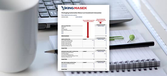
First, start with the numbers. Download our free packing machine ROI calculator to learn how long it will take for an investment in automation to pay for itself (and much more).


Free packaging automation ROI calculator